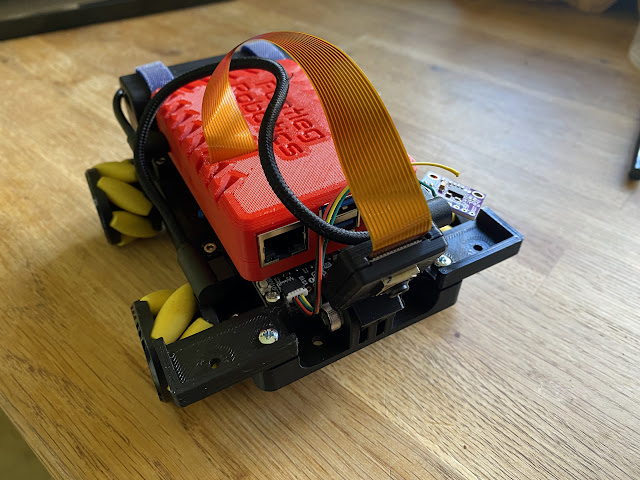
A few more late nights working to assemble my robot. Thankfully the CAD model went together pretty well, with just some minor filing of parts to make them fit together well. I used hot melt threaded inserts in several places which makes it very quick to assemble (and more importantly take apart) when things go wrong.
Some frantic study of the Motor2040 board documentation and schematic revealed no broken out pins from the GPIO. There were some analogue inputs, but it turns out these are for a seperate ADC chip and not the RP2040. Then I spotted the UART pins labelled RX and TX on the board. Looking at the schematic these are directly connected to a pair of GPIOs on the RP2040, and I was not using them for serial communications as I am using the USB socket for that! I clipped my PicoScope probe ground to the USB plug (the only accessible GND point with my board mounted) and found a simple servo driving example for MicroPython. Setting the RX and TX pins as the 'servo outputs' in the example I was able to confirm the PWM output on these pins on the PicoScope. The day was saved!


No comments:
Post a Comment