Thursday 14 March 2019

A Complete Rebuild in Acrylic

It was always my plan to make my competition robot in transparent laser cut acrylic, so that the insides could be seen. Plus it just looks so nice! Having learned the art of designing and building a laser cut robot using 3 mm plywood I was now ready to re-cut the refined design in acrylic. The main modification I made was to shorten the legs by 15 mm. I had realised from driving my prototype that it really did not need such high ground clearance as the small wheels could not climb over anything but small obstacles. It was also a little unstable. I could get it to lift some of the wheels off the ground doing sharp turns at speed!

I added some engraving to various parts and also added holes for threading all the motor and servo wires through the legs. I had drilled these holes by hand on the wooden model. Now I knew where I wanted them I added them to the CAD model so these could be laser cut on the acrylic parts. I had already designed an acrylic mount for my main display and had this mounted on the wooden chassis.

With so many parts to cut I wanted to make optimum use of my acrylic sheet material. So I used an online SVG nesting tool to layout the parts. I prepared an SVG file of all the parts in Inkscape, including a containing rectangle required by the nesting tool to limit the area and shape to fit the parts into. I uploaded this to https://svgnest.com/ which generated a cutting layout for me to download.

An optimised parts layout for laser cutting

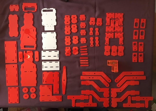
The complete set of laser cut acrylic parts ready to assemble

First I assembled the 4 steering legs. One snag I ran into is the inconsistency in thickness of acrylic sheets. A 3 mm sheet can vary in thickness between around 2.8 mm and 3.2 mm. This is due to the surface tension on the sheet when it is being cast, which results in a curved top surface dipping down towards the middle of the sheet. The sheet sizes you typically buy are cut from this larger cast sheet. Depending on which part of the cast sheet your piece was cut from you get different thicknesses across your piece. Some of my sheets exceeded 3 mm thickness towards one end, so some of my parts did not slot together as all my slots are cut at 3 mm wide. I had to re-cut a few parts with slightly wider slots. But I did not want to make all my slots wider by default, particularly the motor mounting plates which wobbled too much when the slots were not a tight fit. This an area which could do with some more refinement so that the rigidity of the motor mounts is not so dependent on tight tolerances. In the process of assembly I accidentally snapped one part in half and cracked another by over tightening the bolts holding the parts together. Acrylic is a much more brittle material than plywood and is easy to crack, especially around rectangular holes with sharp internal corners. I later modified some of my parts to increase the width of material around the outside edges of the slots from 3 mm to 4 mm to increase the strength of some parts. After re-cutting (plus a few spares) I had two completed Rocker Bogie arms.

The Rocker Bogie arms remade in acrylic with cable routing holes

As I assembled my robot using the new parts, I tried to extensively photo-document every step of the process. My plan is to write up a full build guide and possibly release a kit of parts for others to build their own rover from my design.

Some of the many photographs I took to document the assembly process

Another problem which came from switching to acrylic was that the plates did not grip each other like the plywood had. Some of my chassis body side plates were not staying together at the ends furthest from the bolts holding them in place. I had to add some additional T-slots and bolts to hold everything firmly together. I had designed a new front plate to mount a Pixy2 camera on, and this was not held on with anything more than the friction of the tabs in the slots. This would need more refinement for the competition as it was also going to be holding my Pi Noon attachment and I did not want that falling off mid-battle. For for now I could push it on and it looked good enough for me to shoot some photos. I set up my filming lights to provide some nice back lighting and took a few photos to try and capture the beauty of the acrylic design.

My final photo submitted for the Pi Wars 2019 program

Wednesday 13 March 2019

Another Redesign: Electronics Cartridge

One problem I identified with my robot chassis design was that I could not access any of the electronics without taking the whole thing apart. It was not possible to remove the SD Card from the Raspberry Pi without unscrewing the Pi either. One option for the SD Card access which Brian Corteil suggested was to boot the Pi from a USB thumb drive instead. I had not realised this was possible, but some testing with various tiny sized USB memory sticks showed this worked very well (at least with the Pi 3b). But I was still concerned that if I had any wiring problems on competition day it would be difficult to access the internals to fix things.

The idea I had to solve this was to redesign my chassis so that all the electronics were mounted on a plug-in cartridge which could be pulled out of the chassis to easily access everything. This also allowed me to design a second tier to mount breakout boards on above the Raspberry Pi.

CAD model of my electronics cartridge

Having a 2 tier electronics tray posed some problems with how to route the ribbon cable which connects the touch screen display to the Pi. I went through a few iterations before building a prototype cartridge. If I routed the ribbon cable straight up through the upper tier then it limited the space to arrange the breakout boards on that tier. I ended up with a design where the ribbon cable was folded to change the orientation through 90 degrees from the Pi to the display. The fold was contained on the lower tier, which required the height of the lower tier to be higher than originally planned. Space was tight for the upper tier, and I did not take into account the height of the Du Pont connectors used to attach all the wires to the breakout boards. Another redesign of my entire chassis was required to allow another 5mm of head room. I modelled just one Du Pont connector with a wire bending over coming from it (you can see it in the CAD model above) to check I had the required headroom for the wiring.

Redesigned chassis with the electronics cartridge inserted

It all looked great in CAD, but when I came to assemble it I realised I needed a lot longer cables to provide enough slack to actually slide out the cartridge from the chassis. My ribbon cable was not long enough and 40 way ribbon cables seemed very expensive when I looked online at the usual electronics suppliers. Then I remembered somebody had pointed out that IDE hard disk cables in older PCs were just this type of cable. I checked my box of parts for modding PCs and found I had several. They all had 3 connectors, but I simply cut one off close to the middle connector to give a suitable length ribbon cable. All my other Du Pont connector leads I was making myself from a reel of ribbon cable, so I made these long enough to provide some slack.

The reality was that all this extra cable took up a lot of room, and the cartridge was very tightly packed when assembled. It was very hard to slide out due to the cables all catching on bolts, and in hindsight I could have done with another 10mm of head room in the chassis. But I can just about slide it out with a lot of cable wrangling if required to plug in a new lead. I later extended the i2c breakout to a second bus board near the front of the chassis so that I could easily plug and unplug additional ic2 devices mounted on the front of the robot without needing to remove the cartridge.

The assembled electronics cartridge with the multiple folds in the long ribbon cable. Most of the i2c device cables are missing here, apart from one connecting to the PWM breakout used to drive the servos and motor power. The 4 servo cables are also missing here.

Shown with the chassis front and front-side panels removed. The cables completely pack out the space in the cartridge.


Tuesday 12 March 2019

Robot Software Design

I went for a modular design for my robot software. Python is very modular in structure, with each module importing the modules (or code libraries) it requires. I designed my robot software along the following lines.


Each module does a specific job, and is accessed through a few simple functions which describe the operation being performed. For example the Sensors module contains a function readDistance(sensor) which returns the distance measured by one of the TOF (time of flight) sensors. The parameter (sensor) specifies which sensor (by number) to read. The module also provides the required methods to configure and initialise the sensors, and the i2c multiplexer board they are connected to. So all the complexity of switching i2c buses, turning on sensors and reading them is wrapped up in a module with a very simple code interface.

Another advantage of a modular approach is that you can put all the code which is specific to a set of hardware (e.g. motor controllers) in a single module. The module then presents an interface with simple methods like setMotorSpeed(motor, speed). If you need to change the motor controllers used in your robot, or want to reuse the code on another robot with a similar arrangement of twin motors then you only need to replace this one module and the rest of the code can be reused without changes.

The hardware interface module is called from a module which represents the movement capabilities of the robot. In this case my robot has steerable wheels, and multiple motors wired up in two groups. So the movement control of the robot is wrapped up and controlled through a few simple functions:

  • setLeftMotorPower(speed)
  • setRightMotorPower(speed)
  • setSteering(angle)
  • setSpotTurn(angle)

The LED Matrices module handles setting up and connecting a pair of rgb 5x5 LED matrix breakouts, and displaying patterns on them. A series of patterns are stored in the module and can be called by name. There is also a frame buffer which allows series of patterns to be queued up to show on the LEDs one after the other. Methods can be added to queue up patterns by name. e.g. showBlueEyes() or eyesBlink(). Animations cycle through the frames in the buffer for each display when a nextFrame() method is called.

The main program module handles output onto the main display screen. It also contains all the event handler functions for controller input. A separate module handles detecting different game controllers and mapping their buttons, sticks, hats and triggers to the same named events. So a range of game controllers can be used on the robot and they will all call the same code when their 'triangle button' is pressed.

The main module also contains the code for reacting to touchscreen input to display and navigate through graphical menus, and the main program loop which takes actions based on the mode the robot is in. In this main loop, sensors reading calls can be made, there is the call to display the next frame on the LED matrices, and trigger calls to any event handlers for the connected game controller.

Developing all the code for menus, modes and linking controller input to the robot can be very time consuming when trying to test on the robot itself. But by having the modular structure we can create a virtual copy of our robot, or Digital Twin. By writing a mock copy of each module which interfaces to the actual hardware we can work on the code without the robot being present at all. I did a lot of the coding on a laptop using Raspbian x86 running in a VirtualBox VM. Coding anytime, anywhere. Only the laptop was needed to write, debug and test much of the code.


Just 3 modules (coloured blue above) needed mock versions to the written for the robot to be virtualised. Each of these mock modules has the same name and functions in it as the real version. But the code inside the functions captures the display object from pygame and renders a representation of itself onto the display.

Digital Twin: A virtual representation of the robot
(Background Mars image from Hubble Space Telescope. Credit: NASA)

The mock hardware interface module renders the shape of the robot, and shows the motor speeds and steering leg angles. The mock sensors module generates randomly varying distance readings and renders yellow triangles to indicate the sensor values. The rgb LED matrix mock module renders a representation of each LED matrix onto the screen. I also added an option to display numerical information to aid debugging and diagnosing problems. You can see the virtual robot running in this video clip I posted on Twitter:


The graphical representation of the digital twin of my robot and the sensor output was so useful for debugging issues that I moved it from the mock module into the main robot module. All the graphics slow down the main loop so that it does impair the responsiveness of the robot. So I made it possible to switch on and off via the controller. In normal running the display shows a static graphic of a solar panel, as you can see in this video clip.


(Post Pi Wars 2019 competition I published the full source code for my digital twin robot on github. You can play with my virtual robot using the code on the 'mock' branch. Full instructions and code here: https://github.com/Footleg/PiWars2019/tree/mock )

Monday 11 March 2019

First Fully Drive-able Build of my Mars Rover

My first prototype body to mount my rocker bogie arms onto made me realise I needed to better balance the weight of my robot over the main pivot axis. I also needed better clearance between the body and the steering legs. Then there was the challenge of where to put the rest of the electronics and the battery. I decided the battery was the thing to provide the weight to counter balance the body, and being a heavier item should also be located closer to the ground to make the robot more stable. So I drafted a design where the rear of the body was tapered giving less width. Enough to accommodate the battery but narrow enough to give sufficient clearance for the rear steering legs.

Early redesign of main body with narrower rear end

In attempting to wire up all the motors, and with the steering servo cables also needing routing into the chassis body, my robot was suddenly looking rather messy. I had deliberately made my prototypes from 3mm ply so they could be modified easily to iterate on the design. I explored ways to route the motor wires by getting out the drill.

Iterative design: wire routing!

Somebody commented on one of my Twitter posts asking where I planned to mount the Pi Noon attachment required for two of the challenges. This was not something I had considered up to this point. The challenge rules stated the attachment point had to be on the front of the robot, in the middle. My robot design at this point had nothing but thin air in that position! I wondered about making some sort of brace which attached to the two front rocker arms to hold it. This would lock the rocker (but the event would have a flat surface so not a big issue). Then I realised it was also needed for the Spirit of Curiosity challenge and this was expected to have terrain of varying difficulty. This was the challenge my robot was built for, and my robot was based on the namesake Mars rover of this challenge. I needed another plan. Looking at pictures of the real Mars Curiosity rover I realised that the rocker arm linking bar was positioned forwards of the main pivot axis, rather than behind as on my rover. I swapped mine to the same (you can see this difference between the original animated CAD model and the actual plywood first prototype in my earlier post).

Redesigned chassis shape with battery compartment and room for breakout electronics

Looking at my remodelled chassis it suddenly struck me that the back looked awfully like a front now, and what I had always imagined as the front was looking much more like the back (complete with USB and ethernet 'exhaust' ports). This now gave me a front panel to attach the Pi Noon attachment to as well. I extended the new front end to bring it level with the end of the rocker arms, and so my final rover shape was decided.

The new completed chassis built and ready for some road testing

Checking the A4 footprint of my new design

Finally I had something I could road test. The closest thing I had to some martian terrain was a load of rocks and fossils collected on family trips to the Jurassic coast.


Overall I was very pleased with how well my robot handled. It was very easy to control. The grip on steeper slopes was not enough, but I think for the Pi Wars challenges it will be sufficient. It was a little top heavy and prone to toppling over on more challenging obstacles. Here are some of the out-takes.