Thursday 24 August 2017

Building Our First Robot

Using the CamJam Robotics kit and a Raspberry Pi, the kids and I has started building our first programmable robot. As this was my first adventure with the Raspberry Pi, I kept the cost to a minimum and used a Pi Zero. If you are serious about getting into building and controlling hardware from a computer, I would really recommend starting with the full size Pi 3 model, as it will make setting up and prototyping experiments easier. You can read the post about my recommended Pi 3 set up for my recommendations on what to buy if you want the fully featured Pi. If you decide to start out with the cheaper Pi Zero, then see my post about the challenges of getting started with the Raspberry Pi Zero.

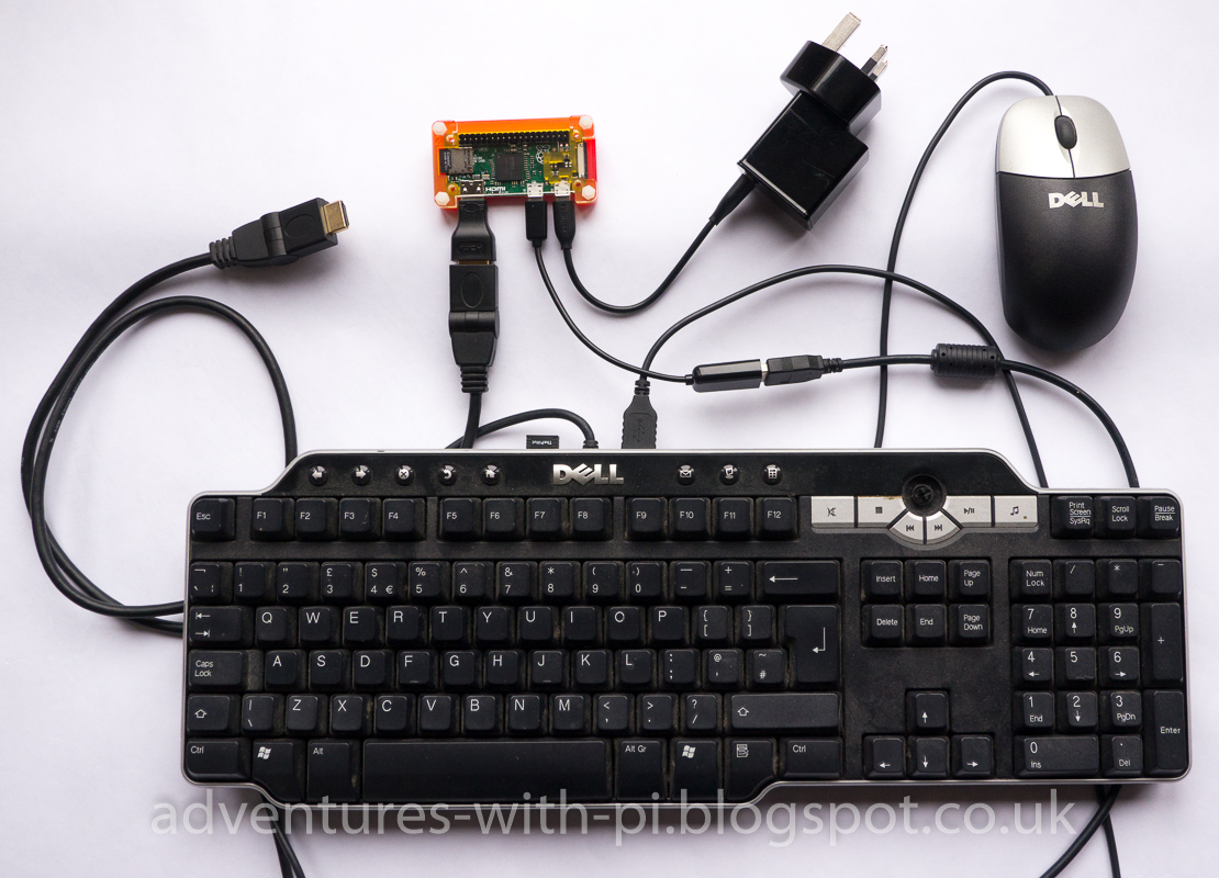
Here is a picture of the parts for our first robot:

This is what you can see in the picture:
  • USB Powerpack (portable battery to power the Pi)
  • Raspberry Pi zero (in a case)
  • USB Wifi dongle, and adapter to fit the mini USB port
  • CamJam Edukit #3: Robotics
  • 4 x AA NiMH rechargable batteries
  • Micro SD card (8GB or larger)
In order to initially configure the Pi zero, you'll also need a keyboard which can be plugged into the single micro USB port on the Pi, and a mini HDMI to HDMI adapter plus an HDMI lead to connect a TV or monitor. Once you have it configured you can remove the keyboard and display, and connect remotely over the WiFi network from another computer. This allows you to program your robot without having it connected to anything by cables, so it can roam freely around the room (or anywhere within range of your WiFi network). In addition to connect the robot interface board from the CamJam kit, you will need a male 40 way header which you'll have to solder onto the Pi zero.   See my post about on getting started with the Raspberry Pi Zero for full details of the initial set up. If you don't want to have to solder anything then you can build this same robot kit using a Pi 3 instead, which has both built in WiFi and the 40 way header already attached. (Since I wrote this, the Pi Zero W board has been released. This is like the Pi Zero but has Bluetooth and WiFi built in. You can also get a 'hammer in' header if you are not ready for soldering. See supplier links for details where to buy these).

After the initial set up of the Pi, you will have access to it from a computer over a wireless network and can start building the robotics kit. At this point I was able to get the kids involved, starting with opening the CamJam Edukit box to see what was inside. My children are aged 9 years (girl) and 6 years (boy). We built our robot using the box that the kit came in. The motors can be stuck onto the bottom of the box and the wires threaded through holes in the bottom of the box to attach to the interface board screw terminals. Then the Pi and the batteries can all go inside the box and it is ready to program and roam around the house. My children enjoyed sticking on the motors and threading the wires. I helped them connect it all up correctly. The worksheets for the CamJam kit (which you can download here) walk you through all of this.


The first step is to load a script to get the robot to simply move in a straight line. This is done by calibrating the scripts so that the motors run at the same speed. My children are not ready to be exposed to Python code yet, so I talked them through what we wanted to do, and asked them questions about how the robot was behaving as we calibrated the script. The code controls the motor speed by sending a pulse width modulated signal to the motors. This is a square wave and we are varying what percentage of the time the voltage is high compared to zero in the waveform. 100% high would be sending full power to the motors all the time. 50% high would send half the power, making the motors run at a slower speed. So we started with 50% and saw that the robot drove along a curved path. At this point I asked the kids why it was not going in a straight line, and nudged them towards the answer that one motor was running faster than the other. I got them to work out which one was going faster. We then reduced the power slightly to that motor and run the script again so see what happened. After a few attempts the kids understood the affect the code changes were having (without having to look at the code) and we had some values which made the robot run more or less in a straight line. I later found that this varied depending on the floor surface. So in the kitchen it behaved slightly differently than on the carpet in the living room.

Next we looked at making the robot turn left and right, again asking the kids what directions we needed to drive the motors to make it turn. This made for a great first lesson for the kids, and a good introduction to programming in Python on the Pi for me. Away from the kids I then set about writing some functions to hide the lower level code so that we could look at some simple Python scripts calling functions to move the robot forward, and turn left or right. With these simpler scripts I was able to show my daughter some code and she could understand how to start to chain together commands to make the robot drive in a square around the kitchen on another day.

Tuesday 11 July 2017

Interfacing the Explorer HAT Pro with Scratch

Looking for a way to get started with younger children in interfacing simple electronic circuits to the Raspberry Pi with Scratch, I learned that the Explorer HAT Pro from Pimoroni is supported in Scratch. Once everything is set up and configured this provides a great beginners platform for driving LEDs, buzzers and motors from Scratch programs, and enabling sensors and inputs to be read from within Scratch. Perfect for little coders in my school code club and protecting the Pi from damage due to circuit design errors. But getting this working in the first place was not straight forward, so here is my guide to setting it all up and getting started with some Scratch examples.

This post is very much a work in progress as I learn more and uncover new information. So I plan to regularly update it as I learn more. But I am publishing it now because I think it already brings together a lot of information that I have found was not easy to search for online.

Scratch 1.4 (Nu Scratch) in Raspbian Jessie can control the built in LEDs, the 5V inputs and outputs, and the motor drivers on the Explorer HAT Pro. But it cannot detect the capacitive touch inputs. The HAT was also a bit temperamental in starting to work with Scratch. I had to open and run the example from Motors and Sensors first before it started behaving. I am not sure that example contains anything my template does not, or whether it just needed a project closing and reopening to sort it out. More testing needed. I started a Vanilla Scratch project template to show how to do everything. One problem is that the ways to switch on the outputs and LEDs do not all appear to work. I can switch LEDs on and off using variables, but not the outputs (which only appear to respond to broadcast messages).

The instructions which cover how to use Scratch 1.4 with GPIO and various supported add on boards can be found here: https://www.raspberrypi.org/documentation/usage/scratch/gpio/README.md

I have uploaded my first Scratch 1.4 template project if you are interested in using it:
ExplorerHAT Vanilla template1.sb

The capacitive touch inputs are supported by Scratch GPIO Plus 8, which can be installed from:
http://simplesi.net/scratchgpio/scratch-raspberrypi-gpio/

This appears to use a slightly different approach to controlling things (setting specially named variables values to turn things on and off). I still need to experiment more to understand how they play together. Some examples can be seen here: http://simplesi.net/explorerhat/
I had to reboot the Pi after installing Scratch GPIO in order to get them to work. I found it temperamental and did not work after I shut down Scratch and reopened it.

Camera support is covered here: https://www.mattvenn.net/2014/12/16/using-a-camera-with-scratch-on-the-raspberry-pi/

Support for capacitive touch sensors is also covered in this article: http://www.pawfal.org/dave/blog/tag/scratch/

Worksheets from NI Raspberry Jam covering Scratch ExplorerHAT Pro here: https://github.com/NIRaspberryJam/Raspberry-Jam-Resources/blob/master/Sections/Explorer-HAT-Getting-started-Level1/

New! Scratch 2,0 offline support on Pi! This example and tutorial covers how to add custom blocks into Scratch to interface to JavaScript, which in turn calls Python code. This should enable support for any add-on boards to be written using their Python libraries.

Following a query I posted on the Scratch Forum I was pointed to http://heppg.de/ikg/wordpress/?page_id=6 ScratchClient, and implementation of a Scratch 1.4 and 2 interface to Python, with lots of adaptors already written for add on boards, and detailed documentation on how to extend this with your own adaptors. Lots more learning ahead!

Tuesday 20 June 2017

First Boot of a Raspberry Pi Zero with Raspbian Jessie Lite

For building a robot, we used a Raspberry Pi Zero with the Raspbian Jessie Lite OS. The robot does not need a graphical desktop running as it is controlled by python scripts, and this combination of low power Pi and low overhead OS should minimise the power needed to be supplied from batteries to run the computer. But it presents some challenges in getting the Pi up and running. So here is what you need to do to get the OS installed, configured and the Pi accessible over a wireless network from another computer. (See the previous article for how to get the Pi Zero set up with the OS installed on the SD card ready to power up for the first time).

On booting up, lots of messages scroll up screen, until eventually the login prompt is displayed.


The default user account on a new install is as follows:
Username: pi
Password: raspberry

This gives you a command prompt, ready to type in commands. The file system had already been expanded to fill card on first boot using the latest Raspbian image, but you can check this for yourself using the 'df' command (type: df  then press ENTER). With my 8GB card it displayed the following information for /dev/root

   7344424 1K blocks. 861480 used. 6154748 available

These numbers are in KB, so the 6154748 available means we have around 6GB of free space. This is about right for an 8GB card, as the OS files take up some of the space, and the 8GB does not result quite that much of usable space since the formatting of the card uses some space to store the directory information and index of files. If you find you have much less space then you can use the raspi-config tool to expand the file system to fill the card. To launch this configuration tool, type:
sudo raspi-config

For full details of this configuration tool, see the official documentation.

The first job after booting up is to get the Pi zero online by configuring the wifi network settings. We will do this using the command line text editor 'nano' to edit the network interfaces file. Open this file in the editor by typing:
sudo nano /etc/network/interfaces

Change the line: auto lo, to auto wlan0
Then change manual to dhcp inside the wlan0 block.

Press Ctrl+x to exit the editor, followed by Y and Enter to save the edits into the existing file.

Now we have told our Pi to connect the WiFi network by default, but we also need to give it the details of which WiFi network to try and connect to. This is done in the wpa_supplicant.conf file which we can edit by typing:


sudo nano /etc/wpa_supplicant/wpa_supplicant.conf
(Tip: press the TAB key after typing part of the folder name or filename and it will autocomplete based on matching folders or files. This saves a lot of typing.)

In the editor, add the following to the end of the file:

network{
  ssid="MyNetworkName"
  psk="wirelesspwd"
  proto=RSN
  key_mgmt=WPA_PSK
  pairwise=CCMP
  auth_alg=OPEN
}

Replace MyNetworkName with the actual name of your WiFi network, and replace wirelesspwd with the password for your WiFi network. Exit and save the file as before (Ctrl+x, then Y and Enter).

The other settings in this network configuration are suitable for most current WiFi routers using the more secure WPA2 encryption. They have worked fine with both my BT Home Hub v5 and v6 routers. But if you have an older router or are using other network encryption settings then you may need to change these too. I found the following article useful if you are looking for further details: http://weworkweplay.com/play/automatically-connect-a-raspberry-pi-to-a-wifi-network/

Once we get our Raspberry Pi connected to our network, we want to connect to it using SSH from another computer. This is handy because unless we have a USB hub we cannot have the WiFi USB dongle plugged in at the same time as the keyboard. The newer Pi Zero W model does not have this problem as it has WiFi built in. But assuming we are using the cheaper Pi Zero here, we will need to make sure that SSH is enabled before we disconnect the keyboard. Since November 2016, the Raspbian OS distributions have SSH disabled by default. It can be enabled using the raspi-config tool, which is launched by typing:
sudo raspi-config

In the config tool, select 'Advanced Options' and then 'SSH'. Choose to enable SSH, then exit the tool.

If everything is ready to go, then we will need to unplug the keyboard from the USB socket in order to plug in the USB WiFi dongle. My dongle did not work when plugged into the USB hub socket on my keyboard. Possibly it would work using a powered hub? Before we unplug the keyboard we need to shut down the Pi. Do this by typing:
sudo shutdown now

Once the Pi is fully shut down (the green LED on the board turns off), unplug the power cord and the keyboard. Then plug the WiFi dongle directly into the Pi USB cable, and reconnect the power. When the Pi Zero boots up again if should automatically connect to the network if we got the wifi configuration right. You should see the IP address it has been assigned displayed on the screen.

e.g. 'My IP address is 192.168.1.109 ....' (followed by some alphanumeric codes)

Sometimes two IP addresses are displayed. I am not sure why, but the first one appears to be the one which works OK.

If the IP address is not displayed then the WiFi network connection likely failed. While the Pi is turned on you can unplug the WiFi dongle from the USB port and plug the keyboard back in so you can login and edit the settings files to try again.

Assuming your Pi is now connected to your network, you should be able to connect to is using SSH. I used the free program WinSCP which you can download from https://winscp.net/

Install WinSCP, and use it to connect to your Pi over SSH using the IP address displayed on boot up. WinSCP is a graphical file explorer tool which enables you to copy files between a Windows computer and a Linux computer (our Pi). You can also use it to edit files stored on the Pi using Windows editors. The command terminal program Putty is included in the install, and you can directly launch this from the Login button too. Or once you are connected, you can launch a terminal session using the Putty tool from a button on the toolbar in WinSCP. Here are the options I used for my Pi (which was using the IP address 192.168.1.109 on my network).


Once you have connected using Putty, you will be prompted to enter the password for the pi user. On first login from putty, the OS warns you if you are using the default password as it is a security risk. Anyone could access your pi as root if they can make an SSH connection over your network. You should change the pi account password to something other than the default of 'raspberry' to secure your pi on the network if you are leaving SSH enabled.


Now you can run commands using putty from a laptop. The screen and keyboard no longer need to be connected to the pi zero, except that without a screen connected we do not get to see what IP address the Pi was allocated on your network when it boots up. Often it will keep the IP address it had the last time, but this is not guaranteed with the DHCP configuration. There are tools you can run from a Windows computer to scan the network looking for devices, or you can change the configuration to use a static IP address so you always know what it is. But you need to make sure it does not clash with any other devices on your network. For now, keep the screen connected when you first boot up so you know which IP address to connect to over SSH.

As this is our first boot up of a new Pi, we should update the packages to the latest stable versions. This is done using the command line apt-get tool. First we need to get the latest package list. Type:
sudo apt-get update

If you are successfully connected to the internet then this will get the latest list of packages. Otherwise it will warn you that if could not access the servers. Just because we are connected to the network does not mean that the network is connected to the internet. So check it did manage to update from the messages displayed.

If you only want to update the packages already on your system to the latest versions, then type:
sudo apt-get upgrade
   
To upgrade the Raspbian distribution to the latest version (which will update all the packages and also remove redundant ones), you type:
sudo apt-get dist-upgrade

This distribution upgrade can take some time (over an hour), so run it when you don't want to use the pi for a while. Keep an eye on it, because you get some information on changes to read once the downloading of new packages completes (my update of a 1 month old Raspbian image after first install took around 2 minutes to download the updates and display the messages which I had to scroll through, then the installation phase of the update started and took another 38 minutes to complete).

Now we have a completely updated OS, we can look at how to get additional packages. You are likely to want to run Python3 scripts, and use the Python GPIO libraries to interface to electronics you connect to your Pi. In the Raspbian Jessie Lite distribution I had, neither of these capabilities were installed already, so here is how to get them.
sudo apt-get -y install python3-rpi.gpio

The package manager will look up the dependencies for the package we are asking to be installed, and automatically install these too. So by just requesting the python3 GPIO package, we will find that Python3 is installed too. Once the install completes, you should be able to type:
python3

The Python 3 REPL environment should launch. You can run python commands directly here. Try typing to following python3 statement at the prompt:
print("Hello Pi World!")

It should display the message in the quotes below the command. You can explore other python3 commands here. When you are done, press CTRL+z to exit REPL and return to the linux shell command prompt. Everything is now ready to start extending your Pi zero and interact with the electronics you connect using Python3 scripts.

Thursday 20 April 2017

Recommended Raspberry Pi 3 Starter Set Up

Based on my experience of buying a range of Raspberry Pi units and accessories, this is what I would recommend as a great set up to get started. It will give you a good prototyping rig for starting to extend the Pi with simple electronics with the minimum of trouble.


The important items to get are as follows:
  • Raspberry Pi 3 (the latest full size Pi at the time of writing this)
  • Official Raspberry Pi power supply
  • Micro SD Card
  • Pimoroni Pibow coupe case
  • Pibow breadboard base
  • Breadboard (5.5 cm x 8.5 cm)
  • USB Keyboard
  • USB Mouse
  • HDMI cable
  • HDMI monitor
Also pictured above (but not essential) is the Raspberry Pi camera module.

The Pibow coupe case keeps all the connectors accessible, and the breadboard base add-on for this case provides a space to stick the breadboard on next to the Pi. I recommend the official Raspberry Pi power supply because it provides enough current (2.5A) to power both the Pi plus additional electronics you might add. A standard tablet charger USB power supply is typically only 2A, which is enough to power the Pi, but may cause it to misbehave if you add any additional electronics which require much power.

Then to give you a great start in building some simple circuits to control, I highly recommend the Explorer HAT Pro, and the Explorer components kits.


You can see these in the photo above, along with the camera module (available separately). The Explorer Hat Pro provides 8 touch inputs and has 4 built in LEDs. It also provides protected inputs and outputs making it less likely you will damage the Pi when prototyping add-on circuits.

The Hat includes a small breadboard for prototyping, but it quickly gets crowded. The Pibow breadboard base and case with a larger 'half size' additional breadboard attached provides a lot more room to build more complex circuits.

Finally, if you have a computer monitor with built in speakers then you can use these to output sound from the Pi 3. We wrote some simple code based on the Explorer Hat Pro examples which lit up a different LED for each touch sensor, and also spoke a phrase (the kids came up with some phrases which we wrote into the code and used text to speech libraries to get the Pi to say them). The kids loved it and it caused much hilarity as the text to speech tried to pronounce what they had programmed it to say.

The components are all available from the usual suppliers, details of which can be found on the links page of this blog.

Sunday 19 March 2017

Getting Started with the Raspberry Pi Zero

The Raspberry Pi zero is a great low cost bare bones board. Costing only £4 (GBP) it is incredible value. A complete computer for just £4? Well not quite, as you really do just get a bare bones board.


It can be a bit of a challenge to work out just how to get started with one of these for the first time. Here we will look at what you need to actually get up and running, and the steps I took with my first Pi zero to get it booted up and connected to to internet in order to use it in our first robot. You need a few additional items to get one of these boards up and running.

First, the computer needs some sort of data storage to read and write files from, and to hold the operating system (OS). These boards use a micro SD card for this purpose. You need at least 8GB of space to install the Raspbian OS. If you need more space to hold lots of files (maybe video files recorded on a Pi camera?) then you might decide to use a larger card.

In order to power the computer, you need some sort of power supply. The Pi Zero will run off the USB chargers which come with most tablets (chargers which can output 2A). Smaller phone chargers may not be able to provide enough power for the board to run reliably. If you don't already have a suitable charger then you can buy a power supply specifically for the Raspberry Pi, or if you are looking to built a robot which is not connected by wires at all then a USB charger battery can be used.

You will need to be able to see the computer output on a screen. To get started, this is most easily done using an HDMI cable to connect it to a TV or computer monitor which has an HDMI input. But you also need an adaptor to connect the HDMI cable to the mini HDMI port on the Pi Zero. Later this can be replaced with a remote computer connecting over a wireless network, but we need to set that up first, so a screen connected directly to the Pi using a cable is needed initially.

You need a keyboard to send commands to the Pi too. This should be a USB keyboard, but you also need another adaptor to enable you to plug the USB keyboard into the micro USB port on the Pi Zero board. If you are using the graphical desktop in the full Raspbian OS then you'll also need a USB mouse. The Pi Zero only has one USB port, so you will need a USB hub of some sort to plug in both the keyboard and the mouse. In my case I had a USB keyboard which had a built-in hub, so I could plug the keyboard into the Pi (via an adaptor cable) and plug the mouse into the USB port on the keyboard.

Finally, in order to connect to your Pi over a wireless network, you will need a USB WiFi dongle. You don't need to plug this in just yet though.

Optional, but recommended is a case for the Pi. Otherwise you have to be careful with a powered on bare circuit board as any contact with metal objects could cause a short circuit and damage it. You can see my assembled set up below (apart from the screen which the other end of the HDMI cable would plug into).


Before you can boot up the Pi Zero you will need to install an OS on the SD card. For our robot we used Raspbian Jessie Lite. You can buy micro SD cards with NOOBS pre-installed if you want to be guided through the OS set up. Or you can save a small amount of money by purchasing a cheap micro SD card (I would recommend getting at least a class 10 card or reading and writing from it will be a little slow). Next download a Raspbian image from the Raspbian website and write the image to the SD card on a computer using an imaging program (I used Win32 Disk Imager on a Windows 10 laptop to do this). Once you have an OS image written to the SD card you can connect everything up and power on the Pi Zero for the first time.

Note that the WiFi dongle is not connected yet. I tried plugging mine into the spare USB port on my keyboard, but the port did not supply enough power and the dongle was not visible to the Pi. However, once we have got the Pi zero booted up and configured to connect to our Wireless network we can shut it down, unplug the keyboard and plug in the USB dongle instead. Then when we boot it up and it has connected to the network, we can connect to it from a laptop to control it. From this point in time we no longer need a keyboard (or a screen) connected to the Pi. See the link at the end of this article for how to configure the Pi Zero to connect to your WiFi network.

If you plan to connect any add-on boards or other electronics to the Pi, then you will also need to solder a 40 pin header onto the Pi Zero board. The full size Raspberry Pi boards come with these already attached.

Below you can see all these essential components laid out with the bare Pi Zero board. In this case a small adaptor shim is shown instead of the micro USB to full size USB adaptor cable. It does the same job as the cable but is much smaller. Most importantly, it must be inserted into the larger USB plug the right way up or you will short circuit the power on your Pi Zero board!


Most of these items can be purchased along with the Pi Zero as an 'essentials' kit from the Pi suppliers. If you are not sure where to buy all the things you might need for your Pi adventures, then take a look at the links page where I maintain links to the websites for anything I have found useful for my adventures with the Pi.

Once everything is up and running, the bare bones Pi Zero only needs the USB wireless dongle and a power supply connected. If something goes wrong with the configuration then having a screen connected is a great help though. Here is my Pi Zero with the header soldered on, the SD card inserted and the whole thing protected with a Pibow Zero case from Pimoroni. The USB WiFi dongle is connected using a shim adaptor. The HDMI adaptor is still connected in case I need to connect a screen, but once it is all working that could also be removed.


In the next article we will walk through how to configure Raspbian to get the Pi Zero connected to the internet over the wireless network, and connect to it remotely from a laptop.

Sunday 5 March 2017

How it All Began

Back in November 2016 I came across an article in Computer Shopper Magazine on how to build your own robot. That sounded like a fun project for me, and also a way to engage with my children on electronics, computers and coding. I had already introduced the kids to coding through the excellent code.org website and their 'Hour of Code' tutorials, and this looked like a great project to tackle with them next. So that was how I was introduced to the Raspberry Pi.

The article was based around the CamJam Edukit #3: Robotics. The parts cost in the article was around £70 (UK Pounds Sterling), but when I looked at what was needed I discovered you could get a Raspberry Pi Zero for just £4 rather than buying the Pi model 3 for around £30. This had the advantage that the robot would not draw as much power from the battery, but meant that some soldering would be required (the CamJam kit used with any of the full size Raspberry Pi models does not require any soldering to build). Doing a bit of soldering was not a problem for me, as I already build electronics as a hobby. So I managed to put together everything I needed for around £56. I already had AA batteries, a soldering iron and tools, and HDMI cable and micro USB lead and charger from various phone and tablet devices.

Here is the robot after my first session assembling it with the kids:

Friday 3 March 2017

Links scratchpad

This is where I am collecting notes and links to resources which I plan to follow up as I explore new ideas and hardware I have ordered. As I make use of these items I will post about these adventures and move the resource links into their own posts.

Suppliers of Raspberry Pi's and hardware to use with them:
Pimoroni: http://shop.pimoroni.com/
The Pi Hut: https://thepihut.com/
Mod My Pi/PiBorg https://www.modmypi.com/
Header cable connectors and tools: http://www.hobbytronics.co.uk/cables-connectors/crimp-connectors?page=1

Books I am learning from:
The Python Apprentice: https://leanpub.com/python-apprentice
Raspberry Pi Cookbook for Python Programmers


LCD Display driving: http://www.raspberrypi-spy.co.uk/2012/07/16x2-lcd-module-control-using-python/

Using the I2C interface: http://www.raspberry-projects.com/pi/programming-in-python/i2c-programming-in-python/using-the-i2c-interface-2

Pinouts for all the HATs I have bought: https://pinout.xyz/

Information on what HATs can be used together can be found on the Pimoroni Forums:
http://forums.pimoroni.com/t/stacking-different-hat-or-phats-on-same-unit/3393

Ideas and Information on Pi Robots

Learning Resources
https://coderdojo.com/resources/

Pi Camera Live Streaming
http://picamera.readthedocs.io/en/release-1.10/recipes2.html#rapid-capture-and-streaming

How servos work and what all the different types are
https://www.rchelicopterfun.com/rc-servos.html