The fundamental components I needed for my raspberry Pi based robot were a Raspberry Pi board, a servo driver board and dual motor controllers. On top of this there would be various sensors and a camera. I decided early on I wanted some sort of display and buttons to control a menu system on the display to set the various modes of the robot for different challenges. The display I chose was the HyperPixel 4.0 touch screen display which Pimoroni had just released. This would give me a beautiful full colour display and the touch screen would enable me to use the screen itself to select menu items.
The next decision was how to power the robot. I had learned from other people of the problems with using a power source for the Pi shared with the motors. If the motors draw too much power then the supply to the Pi can dip, causing reboots or crashes. One way to avoid these problems is to provide a completely separate power supplies to the Pi and to the motors/servos. But this is not necessary provided the power supply can provide enough power for all components at their full loads. I decided to use a high discharge current LiPo battery. I planned to use UBECs (Universal Battery Eliminator Circuit) to eliminate the need for different battery voltages. I could supply 5V to the Raspberry Pi using one UBEC, and 6V to my motors and servos using a second UBEC. I already had experience using the cheap Hobbywing 3A 6V/5V switch mode UBEC for robots. These are readily available online (try eBay). I tend to buy 10 at a time from China so I have a stock of them in my parts box ready for projects.
 |
| Early prototype wiring to test the servo and motor drivers, powered by a LiPo battery and two UBECs |
For the motor drivers, you need to choose some which can supply the voltage your motors require and handle the maximum current which the motors can pull. My robot was using 6V rated micro metal gearmotors with 1:50 ratio gear boxes. According to the listing on the Pimoroni website these have a stall current of 770mA. Stall current is the current the motors will draw if they are fully powered and the shaft is prevented from turning. Typically this can happen if the robot is trying to drive up too steep a slope or into an obstacle which prevents it moving, so all motors could draw this current at the same time. My design had them wired up as 2 pairs of 3 motors in parallel, so I needed a 6V supply to the motors and a maximum stall current of 3 x 770mA = 2.3A. I already had a pair of Adafruit DRV8871 motor driver breakout boards, capable of supplying up to 3.6A per board. The UBEC circuit can supply a steady 3A at 6V so I would need a UBEC per motor driver. I built a test circuit for a single motor and found it did not work. Reading the specifications of the motor driver board again I realised if needed a minimum of 6.5V input voltage. So my UBEC regulating the voltage down to 6V would not work.
Some discussions on Twitter led me to the decision to drive the motors directly off the battery voltage. This could be as high as 8.2V when fully charged, but seeing as the software would limit the motor power using PWM anyway I could set a limit to prevent the motors getting the full power of the battery. They would still be getting peaks of more than 6V during the on-cycle of the PWM signal, but the motors are not such sensitive components that this should be a problem, and I had been advised that these motors could be over-driven safely at these voltages. At a higher voltage I would have more speed, more torque but also a higher stall current. But I would not need a UBEC per motor driver now. The driver boards I had can supply up to 45V to motors, and up to 3.6A so this should work fine.
Next I looked up the HyperPixel touch screen board on the excellent pinout.xyz website to find out which GPIO pins it used on the Raspberry Pi. The answer turned out to be all of them! But it did break out the software i2c bus so I still had the option to control i2c hardware from a Pi using this screen. I was already planning to drive the servos using an Adafruit 16 channel 12 bit PWM servo driver board which is an i2c device, so that should work. But I had no GPIO outputs available on the Pi to drive the motor driver boards. I discussed some options with Brian Corteil of Coretec Robotics at one of the monthly robot club sessions he organises at Cambridge Makespace. These included the following:
- Use an Arduino to provide some additional PWM outputs
- Use a second Raspberry Pi to connect sensors and drive the motors
- Use an i2c GPIO extender breakout board
The last piece of the puzzle was how to drive multiple laser time of flight distance sensors over i2c when the boards I had chosen (the VL53L1X breakout by Pimoroni) had a fixed address. I read it is possible to switch this address on power up, but this presumably required powering up each sensor board in turn, and that would require more digital outputs which I did not have. An easier solution was to use an i2c board which provides switchable i2c buses, and I chose the TCA9548A I2C MULTIPLEXER from Adafruit.
To connect up all my i2c devices, and supply power to the Raspberry Pi, I made a small power and i2c bus breakout board using strip-board. I built this with 5 pin connectors to match the Adafruit PWM board and Pimoroni range of i2c breakouts which all have 5 pin headers including an interrupt line.
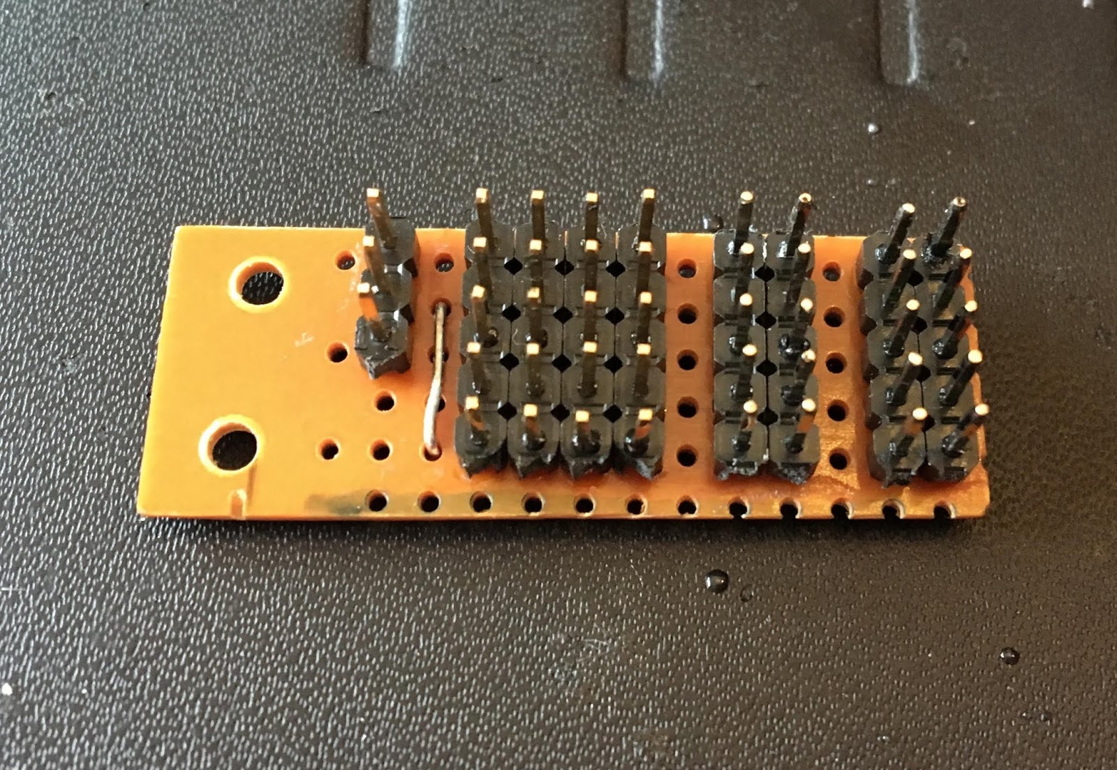 |
| i2c and power bus board |
The UBEC supplying power to the Pi and screen was connected to this, and power supplied over the i2c V+ and GND lines to all components. You can see the complete wiring diagram below.
 |
| The electrical design for my robot (click to see larger version) |
In order to mount the display on top of the robot, I soldered up a right angle GPIO connector using a Pimoroni Pico HAT Hacker board which enabled me to connect the display to the Raspberry Pi using a ribbon cable. I soldered a second 4 wire ribbon cable onto this connector to supply power to both the Pi and the display, and to connect the software i2c bus to my breakout bus board. I was relieved when I connected this all up and saw it working as intended.
 |
| Working display and Pi powered via the i2c bus and power breakout board |
The next challenge was going to be how to fit all this electrical hardware and connecting wiring into my robot chassis.
Hi, I am curious how will to run those vl53l1x. For such reason (not being able to run more than one on the same i2c) I opted for pololu version (https://coolcomponents.co.uk/products/vl53l1x-time-of-flight-distance-sensor-carrier-with-voltage-regulator-400cm-max) which has XSHUT. XSHUT is practically 'reset' - when held active (low?!) device just doesn't work (is in reset mode). If you have gpio connected to it (one vl53l1x needs it and another can be always enabled) - it lets you program i2c address of one that's not in 'reset' state, release XSHUT and program the one that just came online. My sequence is (if i2c address of vl53l1x is 0x29): check if there is anything on 0x30 and if not activate XSHUT ensuring that only one device responds on 0x29 (move it to 0x30, release XSHUT and move 0x29 to 0x31) otherwise if there is something on 0x30 then check 0x31. If 0x31 doesn't have anything then I try to move 0x29 to 0x31.
ReplyDeleteI am very interested if you find a way to make i2c address of adafruit boards 'stick'. Not sure how to deal it otherwise except the way you said: with i2c mux... Here's an idea for multiplex :) http://piwars.abstracthorizon.org/posts/2018/12/10/i2c-multiplexer/
Cheers,
Daniel
I am not aware of a way to make the i2c address change stick for these breakouts. I guess you could just turn each one on in turn and keep them on the same address. I opted for the mux approach because I have no free GPIO pins to use for switching (my display uses them all). So there was no easy way to reset them or update their addresses on power up. I also didn't want to have some complex sensor initialisation code to run each time I needed to reboot my robot (I saw more than a few unplanned reboots during the competition last year as robots got bashed about on the challenges).
Delete