Tuesday, 22 October 2024

Setting up Author Attribution for Mastodon on a Blogger Blog

Mastodon, the open source/not owned by corporations social media platform recently added a feature called Author Attribution, which enables you to set up websites you own so that any link to one of your articles posted by anyone on Mastodon will show an author attribution link below it. This links the article to your Mastodon profile. Here is an example for a link posted to an article from this blog, as it appears on Mastodon.

That 'More from' link below it is the automatically generated Author Attribution link.

To set this up for your websites is a two step process. The first step is to add an author attribution meta tag to your website. This takes the following format:

<meta content='@drfootleg@fosstodon.org' name='fediverse:creator'/>

Of course you need to put your own Mastodon profile link in the content field, instead of my profile. 

As I host my blog on Blogger, I was not sure how I could put this custom meta tag into my blog site. Searching for information online took me to many posts all telling me about the support for meta content tags on Blogger. But these all pointed to the 'Search Description' meta tags section of the Blogger site settings page, and this does not allow you to set the name field (it just provides a way to add the text for the contents field of a description meta tag). So we have to get a little more hands on, which I found you can do by editing the HTML of your page theme.

Instead of 'Settings', you need to select 'Theme' in the left pane of the Blogger site editor page:


Then on the Theme page, look for the 'Customize' button at the top of the page, and select the downward pointing arrow on the end of this button:

This reveals a drop down menu where you can select the option to 'Edit HTML'. Choose this and you will be taken into the theme HTML editor. Up near the top of the HTML you can see the <head> tag. You insert <meta> tags below this. Here you can see the author attribution tag I inserted into my blog on line 6.


Insert your meta tag, and don't forget to click 'Save' on the toolbar. If you now view your blog, and press F12 in your browser to inspect the HTML of the site you should see the tag in your blog site HTML.

That's step 1 done. Now for step 2. This is where you allow your website to be used to generate author attribution links in Mastodon. Go into your Mastodon profile edit screen, and select the 'Verification' setting page. Scroll down past the 'Website Verification' settings (which hopefully you already used to tag your website as a way to verify yourself in the Fediverse?). Below this section you should see the 'Author Attribution' settings panel. Here you add the URLs of all the websites which you want to allow to be attributed to you on Mastodon. Without this part of the process, people could falsely attribute other websites to you. By requiring you to edit both your profile on Mastodon and the HTML of your websites, only you can control which websites are attributed to your Mastodon account. You can see my settings here:

As Blogger can use multiple URLs, I added the two most common ones my blog is accessed from here. Notice this page also shows you the syntax to use for your own meta tag, with a convenient 'copy' button.

That's all you need to do. Now when anyone posts a link to one of your blog articles on Mastodon, it should show an author attribution link below it automatically.


Thursday, 15 August 2024

Using a Game Controller with ROS2 in Docker

(NOTE: Since Pi OS moved from X11 to Wayland, the configurations in this post no longer work. I will update this as soon as I have finished testing and documenting a Wayland compatible configuration.)

Continuing our learning of ROS2 running in Docker containers on top of Raspberry Pi OS (see previous posts in this blog). ROS comes with joystick support in the form of the joy package. https://docs.ros.org/en/jazzy/p/joy/ 
To get this working inside Docker, we need to map our joystick input to our container. In the previous post, we created a Docker Compose configuration file which looked like this:

services:

    sim:

      image: ros_docker:latest

      command: ros2 run turtlesim turtlesim_node

      environment:

        DISPLAY:

        QT_X11_NO_MITSHM: 1

      volumes:

        - /tmp/.X11-unix:/tmp/.X11-unix:rw

    dev-build:

      image: ros_docker:latest

      command: rqt

      environment:

        DISPLAY:

        QT_X11_NO_MITSHM: 1

      volumes:

        - /tmp/.X11-unix:/tmp/.X11-unix:rw

        - ~/ros2_ws:/ros2_ws


Before we try mapping our controller, let’s check it is actually connected to the Raspberry Pi. We are using a bluetooth game controller here. This should work with a PS4 Dualshock Controller, an X-Box One S wireless controller, or an 8BitDo Pro2 controller (which can mimic various controllers). Start by pairing your controller through the Raspberry Pi OS bluetooth tray icon. Select ‘Add Device’, put the controller into pairing mode, wait for it to appear in the detected devices list and then select it and press ‘Pair’.

Once you have a controller connected, type the following command in a terminal:


ls /dev/input


You should see among the various event items, there is a 'js' item.


$ ls /dev/input  

by-id    event0  event2  event4  event6  event9  mice

by-path  event1  event3  event5  event7  js0     mouse0


In my case I saw js0 which indicates my game controller is available as an input device.


Now we can map our input devices into our docker container. I mapped all of them, so any input device becomes available. Add the following section to dev-build service section in the docker-compose.yml file:


      devices:

        - /dev/input:/dev/input


Now we have changed our docker-compose.yml file, we need to stop and restart our container. Docker Compose will detect the change, and destroy the old container and recreate it. So once it starts up again, we will need to source our ROS2 packages again (just once if we put the command into the bash.rc file again). Open a shell in the container:

docker exec -it jazzy-dev-build-1 bash


Then run following command from the shell:

echo "source /opt/ros/jazzy/setup.bash" >> ~/.bashrc


Now exit the shell, and use docker exec to start a new one. You should be able to run ROS2 commands from the shell now. You can also confirm that the joystick input is available inside the container by using the command ‘ls /dev/input’ from the container shell prompt. If you can see the 'js' item then we are ready to use it in ROS.


First, we can use the joy package to list all the available joysticks:

ros2 run joy joy_enumerate_devices


This should list the game controller. There are some gotchas to be aware of here. I found that if my game controller was not connected to the host Pi over bluetooth before I started my container then it would not be detected inside the container after it was connected. So if the controller turns off/loses the connection, then it still appears in the input devices list under /dev/input but does not get detected by ROS. You have to restart the container after reconnecting the controller.


Once you have seen your controller in the list output by the joy_enumerate_devices node, you can start the joy node as follows:

ros2 run joy joy_node


Then in a new terminal, open another shell in your container and run the following to see the outputs from the controller:

ros2 topic echo /joy


This confirms the joy node is posting messages to the /joy topic which you can consume in ROS nodes which subscribe to this topic.


You can also monitor the joy topic in the rqt tool. Open the ‘Plugins/Topics’ menu and select the ‘Topic Monitor’. Tick the /joy topic and you should be able to see the values of the various game controller buttons and joysticks (hold them and wait a little as the refresh rate appears to be only once per second or so in the topic monitor).


Now this is all working, we can try and write a node to subscribe to the /joy topic and make use of the game controller input. We will start with the existing ros2-teleop_twist_joy package: https://index.ros.org/p/teleop_twist_joy/github-ros2-teleop_twist_joy/#jazzy 


We can initially run this directly on our ROS desktop container as it is installed there already. Run the command:

ros2 launch teleop_twist_joy teleop-launch.py


This worked without needing more specific configuration and detected my game controller. It launches the joy node, so you do not need to run that separately. The teleop_twist_joy node subscribes to the /joy topic, and converts the data received from the game controller to 'Twist' data which it publishes to the /cmd_vel topic. In a new shell, you can monitor the /cmd_vel topic:

ros2 topic echo /cmd_vel


The teleop twist node only sends messages when ‘button 8’ is pressed on the controller. This was the left trigger (L2) on my controller. I had to hold it down to see messages in the /cmd_vel topic. 


We can remap the topic name which teleop_twist_joy uses, by passing in a different topic via a command line parameter. So let’s set it up to use the /turtle1/cmd_vel topic:

ros2 launch teleop_twist_joy teleop-launch.py joy_vel:='turtle1/cmd_vel'


You should now be able to control the turtle1 in the turtlesim node, using the game controller. Hold down the enable button (L2 in the case of the default mapping) and the left joystick should be able to drive the turtle around.


Open another shell in the container, and run the command:

rqt_graph


This should open a window showing the node graph. Change the drop down selector to show ‘Nodes/Topics (all)’ and you should see the complete node and topics graph as follows.


Wednesday, 10 April 2024

Final Pi Wars 2024 Blog Entry

It is late in the evening the night before the blogging deadline. So this is my final pre-judging blog entry. I am on holiday in an apartment with no TV. So I had no way to connect my robot to a screen other than to try and get it onto a WiFi connection and VNC onto it from my son's laptop (which I am also using to write this last blog entry). Without a screen to plug into the robot, I decided to try an idea I had but never tested before. I changed the mobile hotspot name on my mobile phone to the same network SID and password as the Makespace network. I then booted up the robot and it connected as it already had the Makespace network set up from working on it there previously. Next I connected the laptop to my hotspot. I just needed to know the IP address the Pi had been allocated. I could not ping it using <robotname>.local so I had to guess the IP. I checked what IP the laptop had on the mobile hotspot, and as the Pi had connected before the laptop I guessed it might have an IP address one bit lower that the laptop. This proved to be the case, and I was able to VNC onto the Pi and work on my code! 

Mostly progress has been in diagnosing why none of my I2C devices were working. After much head scratching I found a note on the Pimoroni website that the silk screen for the 8x8 TOF sensor I was using was incorrect on early boards, and it actually should say x29. The same I2C address as my IMU is using! The IMU can be configured to use x28, but that needs a soldering iron which I don't have with me this week. But at least I could confirm both sensors work when only one is plugged in at a time. I can work with that.

Next I discovered the 8x8 sensor example in MicroPython uses Numpy which is not in the Pimoroni Motor2040 firmware. Ulab Numpy is in the firmware for their Unicorn boards, so I was able to test with that. But in the process of flashing the firmware this wiped the filesystem on the Motor2040 with all my code on it! Thankfully I back things up pretty often. I had all the files on the Pi SD Card, and was able to restore them all apart from one. I managed to download that from my NAS at home over the internet. So everything is back in place. Unfortunately the Unicorn firmware does not contain the motor and encoder classes I need. A cry for help to Pimoroni software expert Gadgetoid resulted in him building a custom MicroPython firmware build which includes the ulab Numpy modules. Now that is customer service! He warned me it will wipe my filesystem, but as I've already been there I am good to try it. Except I had a blog to finish, so I've not done any more coding yet. Plus I am here to relax, after all!


Sunday, 7 April 2024

My Robot is Hardware Complete!

 Finally I have everything assembled and wired up!


I realised my directly soldered wires were prone to snapping off the PCBs, and I needed headers to plug my servo motors into. Just having a pair of signal wires coming of the Motor2040 board was not going to cut it.


My solution was to design some additional brackets to bolt an I2C distribution board onto. A PCB I designed after Pi Wars 2019 but had never actually used on a robot until now.


This board has 4 pin sockets for I2C breakouts, along with some 5 pin sockets intended for the Pimoroni Breakout Garden boards which use a 5th pin for some other signal functions. This 5th pin for each of these sockets is connected to a header on my board. In a flash of inspiration I realised I could cut the power track to these 5 pin sockets, and by sacrificing 2 of these 5 pin outlets I could wire one of the spare 'signal' pins to V+ from the motor supply 6V line and one to GND. Then I could feed the servo supply voltage, GND and the RX and TX signals into this signal header and supply each of the remaining 5 pin sockets with high current power, GND and the signal line needed for the two servos. An extended custom lead crimping session saw the 2 servos converted to custom 5 pin JSH-PH plugs. A custom lead to supply the power and signal inputs to the board, and my servos were connected!

All that remained was to connect up the I2C input to the Motor2040 board and plug in my sensor and IMU and I was done. It was late in the evening the night before my week long family holiday and my robot was read to take away and maybe do some coding on in the evenings. Then the QWIIC socket broke off the Motor2040 board as I plugged in the final connector. I realised I it was too late to take everything apart again, and took the sensible option of going to bed to sleep on the problem.

In the morning, alongside final packing I managed to take apart the robot to remove the Motor2040 board. It has headers which can take a Breakout Garden socket (too large for the space I had) but also due to an extra GND pin on the header, could take a 4 pin JST-XH socket. Genius on the part of Pimoroni, or just good luck? Either way I was able to solder on a socket and crimp up one more custom lead and pack it all in my bag to take on holiday.


Monday, 1 April 2024

Pulling it all together!

 A few more late nights working to assemble my robot. Thankfully the CAD model went together pretty well, with just some minor filing of parts to make them fit together well. I used hot melt threaded inserts in several places which makes it very quick to assemble (and more importantly take apart) when things go wrong.


Here you can see the lower chassis with the Motor2040 board mounted at the front with the battery tray in the middle between the wheels (the battery slides into this). The UBEC sits on top of the middle battery and the USB-C battery pack is on the back, held in place with velcro straps.


The 3D printed Raspberry Pi 5 case sits on top, screwed onto a pair of bars. The screws come up from below and hold the case together, so need to be fitted before the bars are screwed down onto the robot. You can just see the Motor2040 board below the Pi here with an IMU plugged into the QWIIC socket. It was at this point that things started to go wrong. See the yellow wire which has snapped off the IMU board where I had soldered it straight to the PCB. Then I realised my Motor2040 board has no servo headers. I have nowhere to plug in the servos on my grabber!


Some frantic study of the Motor2040 board documentation and schematic revealed no broken out pins from the GPIO. There were some analogue inputs, but it turns out these are for a seperate ADC chip and not the RP2040. Then I spotted the UART pins labelled RX and TX on the board. Looking at the schematic these are directly connected to a pair of GPIOs on the RP2040, and I was not using them for serial communications as I am using the USB socket for that! I clipped my PicoScope probe ground to the USB plug (the only accessible GND point with my board mounted) and found a simple servo driving example for MicroPython. Setting the RX and TX pins as the 'servo outputs' in the example I was able to confirm the PWM output on these pins on the PicoScope. The day was saved!

Friday, 29 March 2024

3D Printing and Assembling my Robot

 Finally I have enough parts printed to start to assemble my final robot.


Some parts require supporting during the 3D printing process. I have an IDEX printer (Independent Dual EXtruder). This means it has 2 independent tool heads/hot-ends. They can each print a different material. So here I have printed my main part in PLA+, but used PETG for the support material. These different plastics do not stick together very strongly, so I can completely eliminate the vertical separation normally required to make supports removable. Above you can see the indented rectangles and the arch (this part was printed the other way up to how it is shown in the photo. The PLA+ is totally supported in these areas, and the PETG just snaps cleanly off (you can see the small PETG supporting parts behind on the desk).

Around 3 weeks to the competition and I have so much to do! I am away for a week around Easter too, so I have to turn this pile of parts into a working robot this week.


It isn't all advanced digital design and manufacturing. I cut these 'washers' out of plastic milk cartons as the polythene these are made of is really low friction. I put one of these between every pivot joint in the grabber so that the rougher surfaces of the 3D prints move smoothly over each other.

Monday, 25 March 2024

CAD Model Completed

After several late nights working on my CAD model I think I have everything done.


Learning from past mistakes, I included a sketch of the maximum allowed robot size. I also used this to label which motor sockets on the Motor2040 board each of my wheels is connected to, so that I reassemble it correctly when I disassemble my test chassis and rebuild it with the 3D printed parts from this new design. I reused the Pi 5 case design, but reprinted it in better quality in ABS. I added mounting space for a USB-C battery pack which after testing I was happy to confirm is capable of powering the Raspberry Pi 5 with no issue. The twin cell Li-Ion battery pack between the wheels powers the motors (via a 6V UBEC) so they get a constant voltage supply whatever the level of charge of the battery. Using separate batteries also ensures the motors don't cause brown outs for the Pi power supply when the going gets tough.

The whole CAD design is highly modular. This enables each part to be printed separately, reducing the time lost if a print fails or a part needs modifying and reprinting. It also allowed me to get parts printing while I was still working on the rest of the model, saving valuable time.

Friday, 22 March 2024

I really need to get working on my own robot!

Just one month to go until competition day, and I have not started building my own robot yet! Panic has started to set in and I have done some initial work on the CAD for a small chassis to hold the motors and a battery. Based on the design of my small tracked robot, but needing 4 motors instead of 2. I have a design which uses commercial camcorder batteries still commonly used for LED video panel lights. So they are easy to swap out and drop onto a charger.


I spent more time than I probably should on designing a model of the mechanum wheels. But now I have them to add to my common robotics parts CAD model library. I will share them on GrabCAD when I have time to think about things after the competition, so that other members of the robotics community can use them in their own CAD models. I'll do the same with the battery model. I have learned it really pays to model every component and put in all the machine screws and hex nuts in the CAD assemblies. This allows interference detection to be calculated and avoids costly mistakes which require re-printing parts when you discover a servo collides with a nut of some such problem when you try to assemble your design for real.

Friday, 8 March 2024

Working on Attachments with my Young Persons Team

Since my holiday coding, all my Pi Wars time has again been spent mentoring my young person's team. Together we designed a barrel grabber to go on the front of their robot, and started 3D printing the parts for their proper robot. By the time we get to competition day, I will have built 4 robots in total! 2 test platforms and 2 actual competition robots. I am teaching my young persons CAD using SOLIDWORKS. We based the grabber off designs we saw when searching for robot claws on eBay and other direct from China tech selling websites. This is what we came up with.


But I have a cunning plan. Having 3D printed all the parts to fit onto their robot chassis, I am going to design the front of my own robot to have exactly the same mounting points. So I can print a second grabber, camera mount and sensor mounting block and put them onto my own robot. Hopefully this will not over balance my much smaller robot. I plan to put my battery on the back to act as a counter balance for the grabber.


Monday, 19 February 2024

Finally some significant progress with my code

On our family holiday to Dorset where we have gone to hunt for fossils on the Jurassic Coast most years since our children were born. By coincidence I find myself working on my robot in the same holiday let conservatory where I worked on my first ever Pi Wars robot back in 2019.


My first objective is to master rotary encoders in MicroPython. It took me a while to get my head around the examples provided for the Motor2040 board by Pimoroni. One example shows how to control velocity of a motor using PID control to adjust the measured velocity from the encoder to reach a desired target velocity. Another example shows how all four motors can be controlled, but this uses an array of motors, an array of encoder classes and an array of PID controllers. It all gets rather complicated and hard to follow. So I refactored these examples to create a PID controlled encoder+motor class. This massively simplifies the code once the constructor has been passed all the complicated parameters needed to assign an available PIO and state machine. The magic happens inside this class, but all you need to do in your program is call the setVelocity method and the PID controller adjusts the PWM duty cycle of the motor driver to get the motor rotating at that velocity by using the encoder in a feedback loop. Velocity control is great because now all motors can easily be set to run at the same speed regardless of small mechanical differences between them and the load due to robot mass or forces due to driving up or down a slope. Meanwhile the code is kept really simple. 

There is another advantage that comes from using PID control, in that you set a target velocity and the PID controller takes the motor to that velocity in a progressive way. So there is some built in dampening which smooths out sudden changes in requested velocity from the driver. This protects the motor gear boxes from excessive strain which can otherwise strip the teeth from cogs in the gearboxes. If you suddenly slam the power joystick from full power forwards to full power reverse, the PID controller starts to adjust the motor power to comply, but does not immediately give the motor full reverse power. It backs off the power a little, measures the effect on the velocity by reading the encoders and re-adjusts accordingly. The driving is still really responsive, but the motors do not break under the strain.

On to the second objective: mechanum driving. I was disappointed to find that the examples for the Motor2040 just set motor speeds to drift left or right, or move forwards or backwards. No omnidirectional drifting. So I looked for information on the internet and eventually found this excellent article with code examples (in C). I managed to reimplement the equations in MicroPython, finding some bugs in their example which had me scratching my head for a few days until I got it all working. Some of my problems where due to me mixing up my motors, and some due to a copy and paste error in the article where they use the wrong variable to adjust for turn input. Now I could move my robot in any direction using one joystick on my controller, while rotating the robot on the spot using the left-right channel from the other joystick. I think this ability to move in 2 dimensions while independently rotating to face in another direction will be really handy in Pi-Noon!

The final piece of the puzzle was to measure the robot heading, so that I could implement field oriented driving. This is where the robot moves in directions relative to the driver position/arena, regardless of which direction it is actually facing. To put it another way, up on the joystick moves the robot up the arena (away from you) and down moves it back towards you. You can spin the robot around to face in any direction and it still moves away/towards you when you push up or down on the joystick. The magic of mechanum wheels in conjunction with matching wheel velocities due to the velocity controlled encoder motor driving, allowing the robot to move in any direction while pointing in any unrelated direction. The robot just needs to be able to measure it's heading, which requires an IMU. Luckily I had been learning how to use the BNO01 IMU chips on my other small robot project (see my earlier blog entry for Piwars 2024). This IMU chip has on-board sensor fusion, where it combines the 3 axis compass, 3 axis accelerometer and 3 axis gyro readings to calculate a 3 dimensional orientation vector for the robot. Using this you can determine which direction the robot is facing at any point in time, and subtract that angle from the direction the mechanum drive equations are being given to move the robot. This provides field oriented driving, which should be very useful in several of the challenges.


Tuesday, 30 January 2024

A New Idea to Rescue My Pi Wars Entry

So I need a new idea for my Pi Wars robot. Something small that will be quick to build. I am a big fan of small robots, although it can be challenging to fit everything in the limited space. For me the value of Pi Wars is that it pushes me to learn and advance. I've never really enjoyed the competitive aspect of things, but I really enjoy pushing myself to improve. So I started thinking about building on the ideas I have been working on using a Raspberry Pi communicating to a MicroPython board with the Pimoroni Yukon, but shrinking things down a little. I have wanted to build a robot with Mechanum wheels for a while now. Mechanum wheels have little rollers mounted at a 45 degree angle all around them, and by driving them in different directions it is possible to make a robot move in any direction without turning the body of the robot to face in that direction. I had all the parts I needed in my 'things I bought in Pimoroni sales but have not had time to use yet' boxes. So I swapped the Yukon board for the smaller Motor2040 board which supports 4 independently controllable encoder motors. Encoder motors are another thing on the long list of topics I have wanted to explore but hadn't found the time yet. So I laser cut a pair of acrylic plates with mounting holes for motors, a Raspberry Pi and a Pimoroni Motor2040 board. I already had some motor mounting brackets I had 3D printed on the Makespace resin printer. 


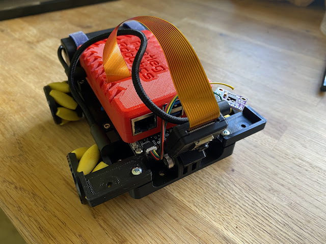
I have a robot! Albeit a test chassis to develop some code on rather than a final Pi Wars entry. I had been designing a case for the new Raspberry Pi 5, so I just mounted that on the chassis. Another step into new learning as the power requirements for the Pi 5 for mobile robotics raise more problems I wanted to solve. The Raspberry Pi 5 also requires running the Bookworm version of Raspberry Pi OS, which means python libraries not included in the apt packaging system can only be installed into a virtual environment. So this would push me to solve the problems of configuring my robot code to run on boot inside a virtual environment. So I will be learning a lot! Now I just need to find some time to work on the code.

Sunday, 28 January 2024

Mentoring a Young Persons Team

Mentoring young persons in PiWars has by far been the most rewarding aspect of the competition over the past 5 years. This year is the 7th young persons team I have mentored through the competition. They have pretty much taken up all my time for robotics during this competition so far, hence the lack of progress and updates on my own robot. Time is always very limited with young persons teams. In the past I have always mentored through running after school robotics clubs in local schools. School safe guarding rules generally mean I only get a hour a week with the teams, and have no way to communicate with them outside of these club sessions. This really restricts what I can do with them. I literally get around 20 hours with them over the entire span of the competition, to help them design, build and code a robot. The exception to this has been the monthly Robot Club run by Brian Corteil at Cambridge Makespace, where I have managed to arrange with the parents of some of the children in my teams to bring their children along and give us some more precious time to work on their robots.

This year is a little different as I was unable to get an after school club organised due to staff leaving and schools closing/merging where I had previously made contacts with staff. But then my daughter entered with a school friend giving me a team to mentor who I could work with outside of school. This has made a huge difference both in terms of what we can do, and in how much of my time they have taken up!

Here they are at Makespace where we went to the Robot Club and built this robot in a day!


It was based on the guts of a robot from last year (my daughter was also on that team). We designed and laser cut a base plate with holes to mount all the electronics and batteries, then mounted everything with machine screws. This is just a working development platform to give them something to start working on the code. We looked at my collection of sensor electronics, and they decided to start with a camera as they plan to try and tackle some of the challenges autonomously. This brings me to the second huge benefit of mentoring young people. They teach you so much! I have never done any image recognition before. I always wanted to explore this area, but never found the time until now. Suddenly I am up to my neck in their Open CV code, trying to understand it, help them debug it and advising them on approaches to problem solving. They have some great ideas, slicing images into vertical strips, calculating average brightness to determine where in the frame the line is for the line following for the Lava Palava challenge. Detecting barrels by colour, and recognising Zombies. Even if I never get the time to work on my own robot for this competition, they have pushed my knowledge far into new areas. It has been great!

Saturday, 20 January 2024

Size Matters

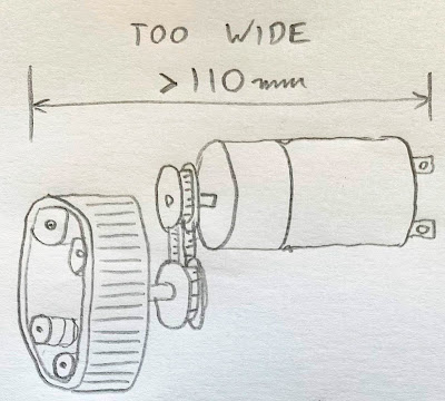
Everything has gone wrong! I've been trying to find a way to make my robot narrow enough to fit inside the Pi Wars maximum allowed robot dimensions. The problem is that the motors I planned to use along with the tracked wheel assemblies are too wide. I was planning on a belt drive mechanism so one motor could drive both tracks on one side of the robot, and the rocker bogie pivot could be the axis of the motor. 

But with these motors positioned back to back there is only going to be room for the tracks within the width if I design a two stage belt system so that the belts driving the tracks are in line with the motor body. 

Another idea I played with was to use 45 degree angle bevelled gears to enable me to mount the motors at 90 degrees to the pivot axis. This would enable me to mount the motors so their bodies were oriented along the length of the robot, rather than the width. I could position the motors closer together this way and get the robot to fit inside the width limit for the competition.

At this point I realised something more significant which had been staring me in the face all along. Placing two of my track assemblies one in front of the other, there is no way to fit them within the length limit for Pi Wars! There would not be enough clearance between them to prevent the front tracks snagging on the rear tracks in the rocker bogie arrangement where each track can freely pivot around it's own axis. I wondered if I could fit them offset from each other, placing the front pair closer together than the rear pair? Then the front pair could overlap with the rear pair. But this consumed too much width again. It was time to accept this was not going to work. So now I need a completely new idea!